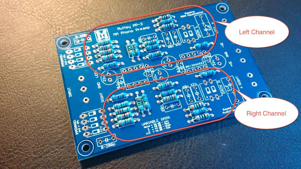
Build the Muffsy Phono Preamp PP-3
The Muffsy Phono Preamp kit comes with all on-board components. Have a look at this page to learn about how to turn it into a complete and fully working phono stage.
You can also have a look at the schematics for the Muffsy products under the Modify It page.
Illustrations Explained
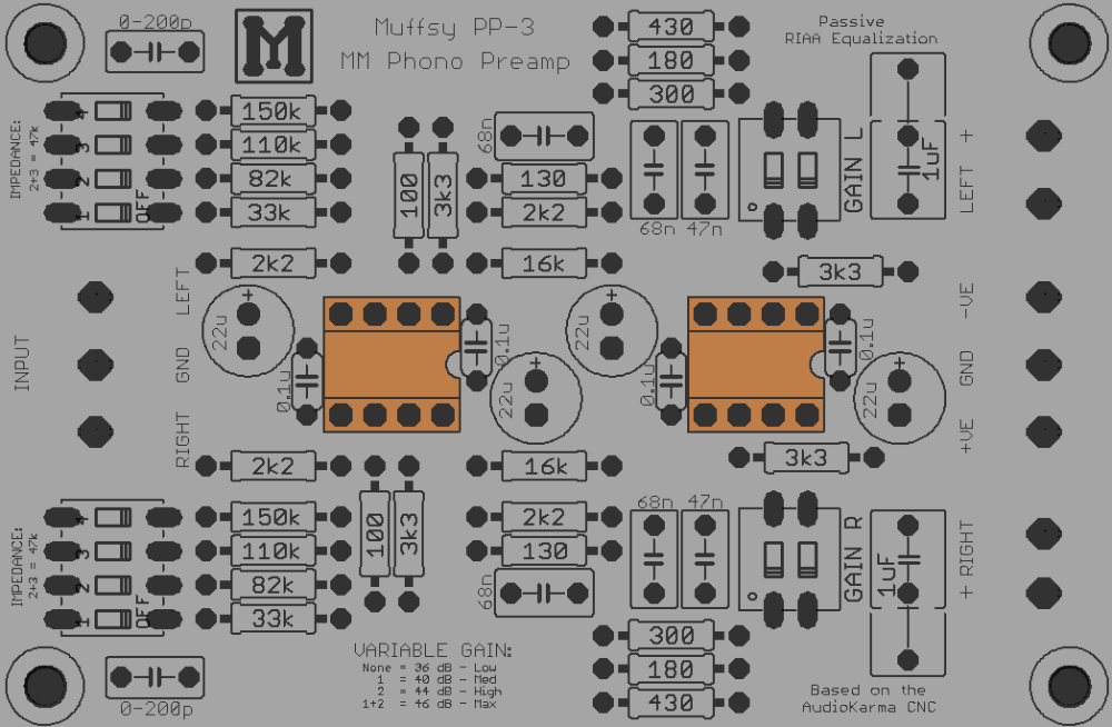
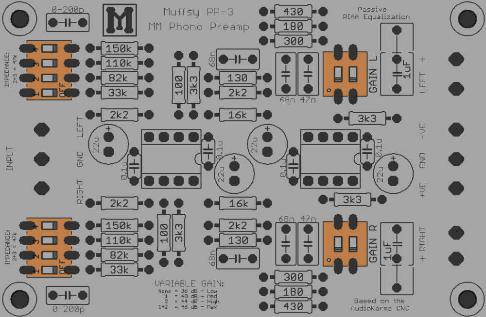
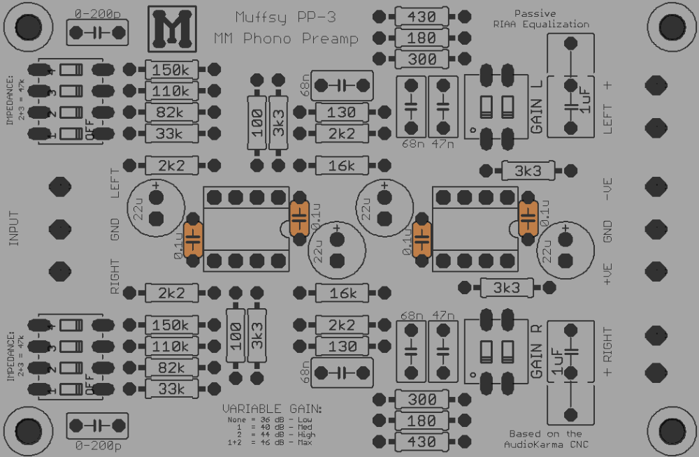
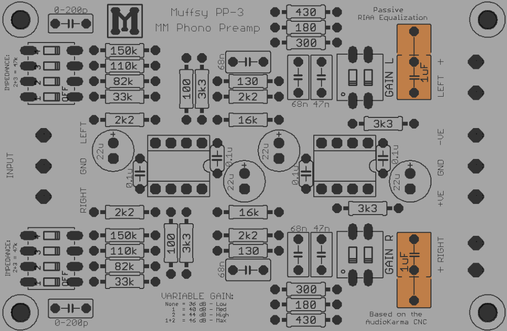
The picture below is a larger version of your printed circuit board. For each step, this will be used to show you which components you will be adding to the board.
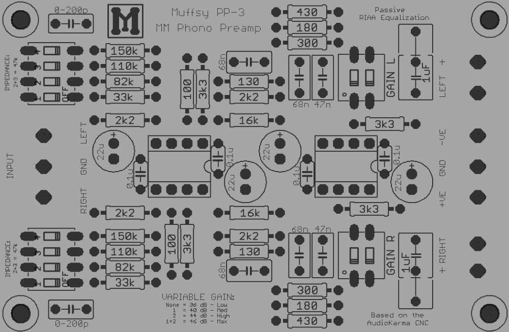
This picture shows you where you are in the build process. It also shows what each component looks like, and it will contain special instructions or information.
Step 1: Check the Kit Contents
Before you start building, check that you have all components and familiarize yourself with the kit. Here's a list of the kit's contents:
| Quantity | Component |
|---|---|
| 1 | Muffsy PP-3 Printed Circuit Board |
| 2 | Resistors 0.25W, 100 ohm |
| 2 | Resistors 0.25W, 130 ohm |
| 2 | Resistors 0.25W, 180 ohm |
| 4 | Resistors 0.25W, 300 ohm |
| 0 | Resistors 0.25W, 430 ohm (replaced with 300 ohm) |
| 4 | Resistors 0.25W, 2k2 ohm |
| 4 | Resistors 0.25W, 3k3 ohm |
| 2 | Resistors 0.25W, 16k ohm |
| 2 | Resistors 0.25W, 33k ohm |
| 2 | Resistors 0.25W, 82k ohm |
| 2 | Resistors 0.25W, 110k ohm |
| 2 | Resistors 0.25W, 150k ohm |
| 2 | 8-Pin DIL Sockets |
| 2 | 2-Way DIP Switches |
| 2 | 4-Way DIP Switches |
| 2 | Operational Amplifiers |
| 4 | Ceramic Capacitors, 100 nF |
| 2 | Polyester Film Capacitors, 47 nF |
| 4 | Polyester Film Capacitors, 68 nF |
| 2 | Polyester Film Capacitors, 1 uF |
| 4 | Electrolytic Capacitors, 22 uF |
| 2 | DG301 Screw Terminals, Two Positions |
| 2 | DG301 Screw Terminals, Three Positions |
All resistors are 1/4 W, metal film, 1% tolerance.
Note:
This high quality printed circuit board has plated-through holes. Do not attempt to drill the holes to make them larger, doing so will destroy the board.
The four mount holes, one in each corner, may be drilled to size.
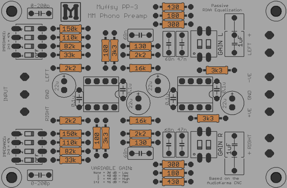
Step 2: Solder the Resistors
There is a total of 28 resistors that go onto the printed circuit board.
The resistors are bidirectional, meaning that you don't have to worry about which way they are oriented.
Before you mount the resistors, have a look at the possible modifications you can make and replace the necessary resistors accordingly.
It's recommended that you measure the resistors before you put them in place, and make absolutely sure that the right resistors go in the correct positions.
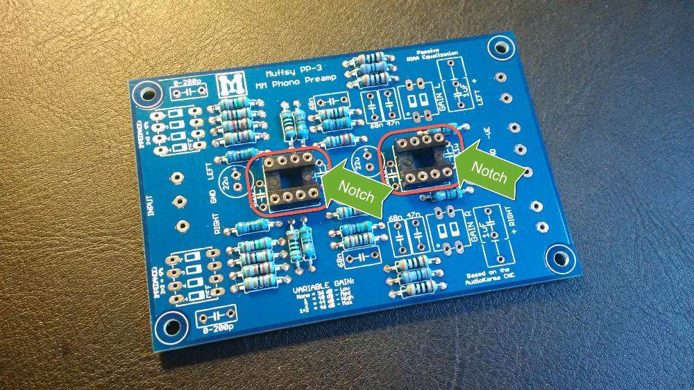
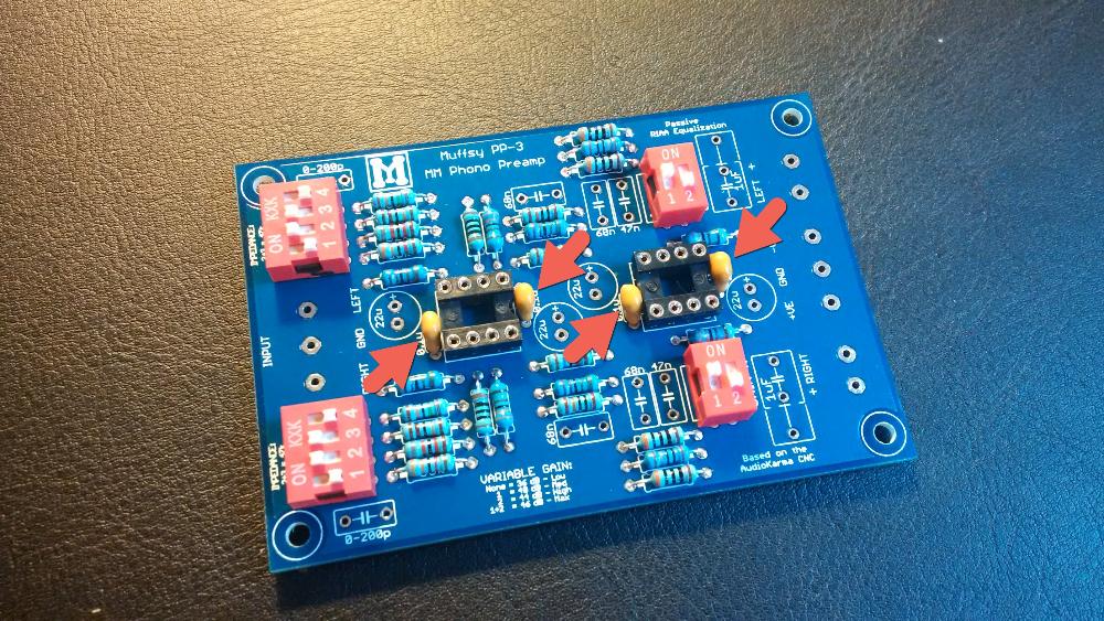
Step 3: Solder the DIL Sockets
These are the sockets for the operational amplifiers. They will make it easier to replace the small chips later on if you should want to. Soldering the sockets will also make sure you don't overheat the operational amplifiers when installing them.
The orientation is very important for these two sockets, get it wrong and you will be confused about which way to mount the operational amplifiers. There's a notch in the socket that matches up with the picture on the printed circuit board, as shown in the pictures below.
Using a piece of masking tape to hold the sockets in place might be a good idea.
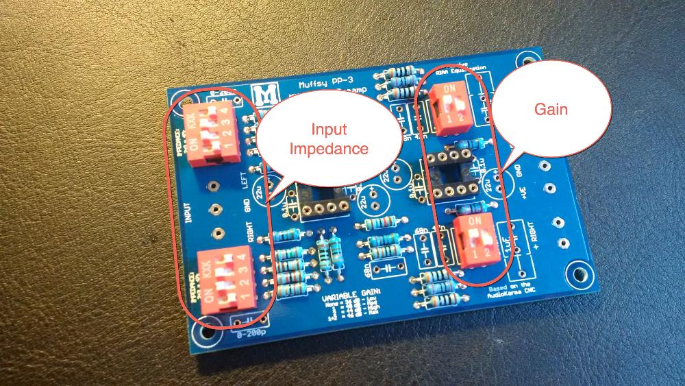
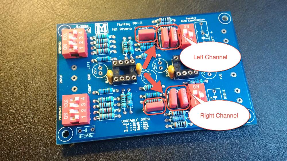
Step 4: Solder the DIP-Switches
These four DIP-switches are here to adjust the input impedance and overall gain of the phono stage.
It is absolutely essential that you get the orientation right. If you don't, adjusting the features of the preamp will be very difficult and confusing.
Use a piece of masking tape to hold the switches in place while you solder.
Now is a good time to set the default settings of the phono stage. Set switch 2 and 3 on the input impedance switches to on, and switch 1 on the gain switches to on. The input impedance will now be 47k ohm and the gain will be 40 dB
Step 5: Solder the Ceramic Capacitors
There are four ceramic capacitors, two on each side of each DIL socket.
These capacitors can be oriented which way you like. I like to mount them so I can see the text on them.
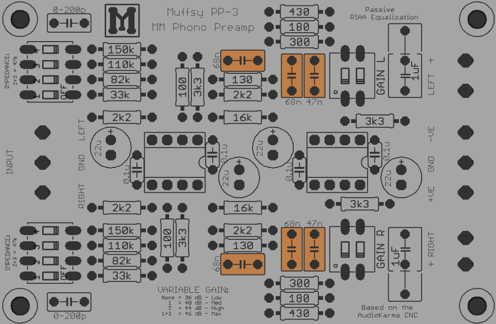
Step 6: Solder the RIAA Polyester Film Capacitors
These are the six capacitors in the RIAA filter.
They are bipolar, so orientation is not significant. I still like to place them so that the text is visible.
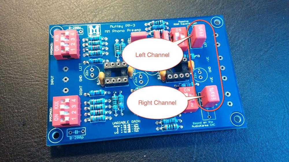
Step 7: Solder the Output Capacitors
These two 1 uF polyester film capacitors makes sure that no direct current (DC) enters into the next amplification stage (preamp or power amplifier).
They can be oriented either way. Note that the PCB has space for two different sizes, 5 and 10 mm lead spacing. One of the legs must be towards the center of the board, and the capacitors must span the "-||-" symbol. The pictures below explains this.
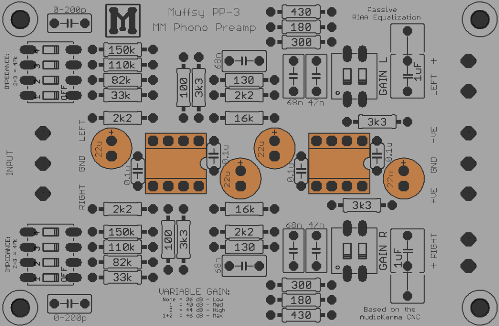
Step 8: Solder the Electrolytic Capacitors and Mount the Operational Amplifiers
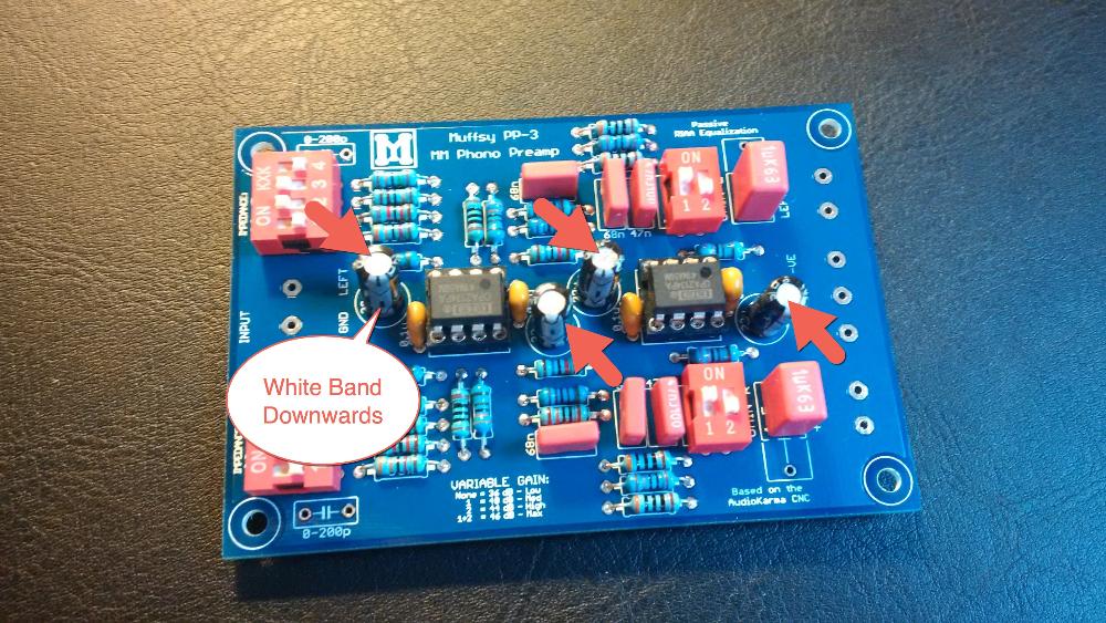
The four 22 uF electrolytic capacitors must be oriented correctly, or there's a chance they will go up in smoke.
The board shows a plus (+) symbol, this is where the longer leg of the capacitors will go. The capacitors have a white band with several minus signs (-), this side also has the longer leg. This side goes downward when the board is oriented as shown on the pictures.
Now is also the time to mount the two operational amplifiers into their sockets. They are small eight-legged chips, and the dot and/or notch matches the notch in the sockets. Make sure they go in the right way, and that no legs are bent so that they miss the hole.
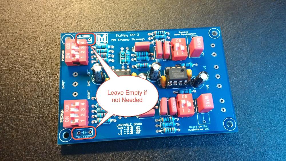
Step 9: Optional - Solder the Input Capacitors
For some very special setups/cartridges, you may need some additional input capacitance. If you do, mount these two capacitors now.
It is very likely that you won't need them, and they are not included in the kit.
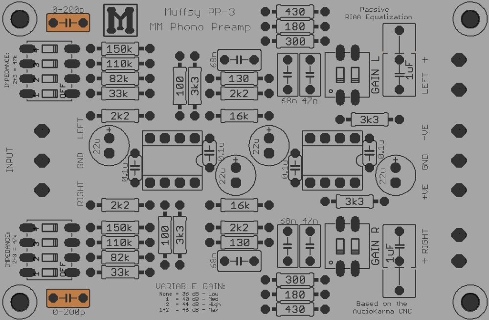
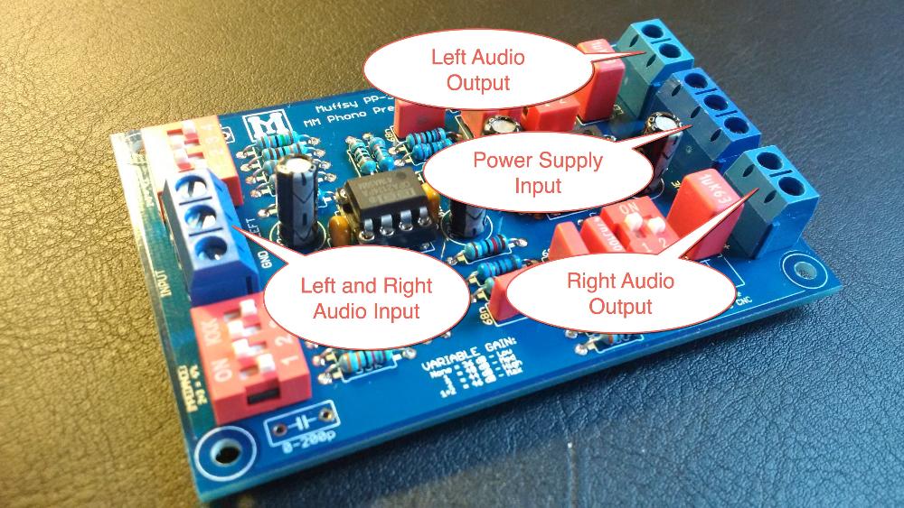
Step 10: Solder the Screw Terminals
These screw terminals will make it easier to connect the power and audio cables.
Orientation of the Screw Terminals
B0905 Cabinet: If you are using a B0905 cabinet, you really want the holes of the screw terminals pointing inwards. If you don't, you risk shorting the cables against the wall of the cabinet.
If you have a lot of space in your cabinet, having the holes of the screw terminals pointing outwards from the board is normally the way to go.
Construction Complete
Congratulations, you have built a phono stage!
To complete your build, continue to the following instructions: